Would you like to produce aerated concrete?
We’ll help!
START YOUR OWN BUSINESS RIGHT NOW!
AAC Line for aerated concrete block production
- Fly ash, 50m3/shift
- Sand, 30m3/shift
- Sand, 50m3/shift
- Sand, 100m3/shift
AUTOMATED PRODUCTION LINE
FOR AERATED CONCRETE BLOCKS WITH FLY ASH AGGREGATE,
capacity 50 m3/shift
Line Specifications
| Capacity | 50 m3/shift (100 m3/day) |
| Power consumption | 54 kW/h (w/o water heating) |
| Water utilisation | ~13 tonnes/shift |
| Cement utilisation | ~12,5 tonnes/shift |
| Fly ash utilisation | ~10,5 tonnes/shift |
| Productions | small wall blocks according to GOST 21520-89 |
| Required production facility area | 500-1000 m2 |
| The ceiling height at the mixing area | not less than 6 m* |
| The ceiling height at the production area | not less than 3 m* |
| Ambient temperature | not be less than +15oС |
| Required personnel | 6 workers, 1 production manager/foreman |
LINES SPECIFICATIONS
|
N
|
Name
|
Quantity
|
|
The area of raw materials storage, preparation, and loading
|
||
| 1 | Cement screw conveyor (L = 6 m*, gear motor (Italy), N = 4 kW) | 1 |
| 2 | Fly ash screw conveyor (L = 6 m*, gear motor (Italy), N = 4 kW) | 1 |
|
Mixing area
|
||
| 1 | Electronic control system (with integrated water meter + booster pump) | 1 |
| 2 | Weighing batcher (strain gauges, pneumatic valve, max. 600 kg) | 1 |
| 3 | DKhD-1 chemical admixtures weigher (N = 0.5 kW) | 1 |
| 4 | GB-0.85 aerated concrete mixer (N = 11 kW, V = 0.85 m33) | 1 |
| 5 | C200LB40 compressor (500 l/min, 8–10 atm.) | 1 |
|
Monolith cutting area
|
||
| 1 | ARK-004 automated cutting complex (N – 19.5 kW) | 1 |
| 2 | FM-0.91 m3 mould for aerated concrete monolith (V = 0.91 m3). | 55 |
| 3 | Transfer cart | 4 |
| 4 | Complex for dismantling of moulds (N = 2.0 kW) | 1 |
| 5 | Complex for stacking blocks onto pallets (N = 2.5 kW) | 1 |
|
Cutting waste grinding area
|
||
| 1 | DG-1 grinder (N = 4.5 kW) | 1 |
MATERIAL CONSUMPTION* PER 1 m3 OF NON-AUTOCLAVED AERATED CONCRETE D-600
| Material | Quantity |
| Cement (PTs500 D0), kg | 250 |
| Fly ash, kg | 210 |
| Water, l | 250 |
| Gas-forming agent, kg | 0,5-1,5 |
| Fibre, kg | 0,6 |
| Chemical admixtures, kg | ** |
* The recipes are adjusted to take into account the properties of raw materials chosen by the customer.
** The type and amount of the admixtures are determined on the concrete design phase.
AUTOMATED PRODUCTION LINE
FOR AERATED CONCRETE BLOCKS WITH WITH SAND AGGREGATE,
capacity 30 m3/shift
Line Specifications
| Capacity | 30 m3/shift (60 m3/day) |
| Power consumption | 42,5 kW/h (w/o water heating) |
| Water utilisation | ~7 tonnes/shift |
| Cement utilisation | ~8,4 tonnes/shift |
| Sand utilisation | ~6,3 tonnes/shift |
| Productions | small wall blocks according to GOST 21520-89 |
| Required production facility area | 500-1000 m2 |
| The ceiling height at the mixing area | not less than 6 m* |
| The ceiling height at the production area | not less than 3 m* |
| Ambient temperature | not be less than +15oС |
| Required personnel | 5 workers, 1 production manager/foreman |
LINES SPECIFICATIONS
|
N
|
Name
|
Quantity
|
|
The area of raw materials storage, preparation, and loading
|
||
| 1 | Cement screw conveyor (L = 6 m*, gear motor (Italy), N = 4 kW) | 1 |
| 2 | VG-1 vibrating screen (N = 3kW, from 1 tonne/hour**) | 1 |
| 3 | Sand belt conveyor (L = 7 m*, N = 3 kW) | 1 |
|
Mixing area
|
||
| 1 | Electronic control system (with integrated water meter + booster pump) | 1 |
| 2 | Cement weigher (strain gauges, pneumatic valve) | 1 |
| 3 | Sand weigher (strain gauges, pneumatic valve) | 1 |
| 4 | DKhD-1 chemical admixtures weigher (N = 0.5 kW) | 1 |
| 5 | GB-0.85 aerated concrete mixer (N = 11 kW, V = 0.85 m33) | 1 |
| 6 | C200LB40 compressor (500 l/min, 8–10 atm.) | 1 |
|
Monolith cutting area
|
||
| 1 | ARK-003 automated cutting complex (N = 13 kW) | 1 |
| 2 | FM-0.91 m3 mould for aerated concrete monolith (V = 0.91 m3). | 33 |
| 3 | Transfer cart | 4 |
| 4 | Complex for dismantling of moulds (N = 2.0 kW) | 1 |
| 5 | Complex for stacking blocks onto pallets (N = 2.5 kW) | 1 |
|
Cutting waste grinding area
|
||
| 1 | DG-1 grinder (N = 4.5 kW) | 1 |
MATERIAL CONSUMPTION* PER 1 m3 OF NON-AUTOCLAVED AERATED CONCRETE D-600
| Material | Quantity |
| Cement (PTs500 D0), kg | 280 |
| Sand, kg | 210 |
| Water, l | 220 |
| Gas-forming agent, kg | 0,5-1,5 |
| Fibre, kg | 0,6 |
| Chemical admixtures, kg | ** |
* The recipes are adjusted to take into account the properties of raw materials chosen by the customer.
** The type and amount of the admixtures are determined on the concrete design phase.
AUTOMATED PRODUCTION LINE
FOR AERATED CONCRETE BLOCKS WITH WITH SAND AGGREGATE,
capacity 50 m3/shift
Line Specifications
| Capacity | 50 m3/shift (100 m3/day) |
| Power consumption | 54 kW/h (w/o water heating) |
| Water utilisation | ~11 tonnes/shift |
| Cement utilisation | ~14 tonnes/shift |
| Sand utilisation | ~10,5 tonnes/shift |
| Productions | small wall blocks according to GOST 21520-89 |
| Required production facility area | 500-1000 m2 |
| The ceiling height at the mixing area | not less than 6 m* |
| The ceiling height at the production area | not less than 3 m* |
| Ambient temperature | not be less than +15oС |
| Required personnel | 6 workers, 1 production manager/foreman |
LINES SPECIFICATIONS
|
N
|
Name
|
Quantity
|
|
The area of raw materials storage, preparation, and loading
|
||
| 1 | Cement screw conveyor (L = 6 m*, gear motor (Italy), N = 4 kW) | 1 |
| 2 | VG-1 vibrating screen (N = 3kW, from 1 tonne/hour**) | 1 |
| 3 | Sand belt conveyor (L = 7 m*, N = 3 kW) | 1 |
|
Mixing area
|
||
| 1 | Electronic control system (with integrated water meter + booster pump) | 1 |
| 2 | Cement weigher (strain gauges, pneumatic valve) | 1 |
| 3 | Sand weigher (strain gauges, pneumatic valve) | 1 |
| 4 | DKhD-1 chemical admixtures weigher (N = 0.5 kW) | 1 |
| 5 | GB-0.85 aerated concrete mixer (N = 11 kW, V = 0.85 m3) | 1 |
| 6 | C200LB40 compressor (500 l/min, 8–10 atm.) | 1 |
|
Monolith cutting area
|
||
| 1 | ARK-004 automated cutting complex (N = 19.5 kW) | 1 |
| 2 | FM-0.91 m3 mould for aerated concrete monolith (V = 0.91 m3). | 55 |
| 3 | Transfer cart | 4 |
| 4 | Complex for dismantling of moulds (N = 2.0 kW) | 1 |
| 5 | Complex for stacking blocks onto pallets (N = 2.5 kW) | 1 |
|
Cutting waste grinding area
|
||
| 1 | DG-1 grinder (N = 4.5 kW) | 1 |
MATERIAL CONSUMPTION* PER 1 m3 OF NON-AUTOCLAVED AERATED CONCRETE D-600
| Material | Quantity |
| Cement (PTs500 D0), kg | 280 |
| Sand, kg | 210 |
| Water, l | 220 |
| Gas-forming agent, kg | 0,5-1,5 |
| Fibre, kg | 0,6 |
| Chemical admixtures, kg | ** |
* The recipes are adjusted to take into account the properties of raw materials chosen by the customer.
** The type and amount of the admixtures are determined on the concrete design phase.
AUTOMATED PRODUCTION LINE
FOR AERATED CONCRETE BLOCKS WITH WITH SAND AGGREGATE,
capacity 100 m3/shift
Line Specifications
| Capacity | 100 m3/shift (200 m3/day) |
| Power consumption | 98 kW/h (w/o water heating) |
| Water utilisation | ~22 tonnes/shift |
| Cement utilisation | ~28 tonnes/shift |
| Sand utilisation | ~21 tonnes/shift |
| Productions | small wall blocks according to GOST 21520-89 |
| Required production facility area | 1000-1500 m2 |
| The ceiling height at the mixing area | not less than 6 m* |
| The ceiling height at the production area | not less than 3 m* |
| Ambient temperature | not be less than +15oС |
| Required personnel | 9 workers, 1 production manager/foreman |
LINES SPECIFICATIONS
|
N
|
Name
|
Quantity
|
|
The area of raw materials storage, preparation, and loading
|
||
| 1 | Cement screw conveyor (L = 6 m*, gear motor (Italy), N = 4 kW) | 2 |
| 2 | Sand belt conveyor (L = 7 m*, N = 3 kW) | 2 |
|
Mixing area
|
||
| 1 | Electronic control system (with integrated water meter + booster pump) | 2 |
| 2 | Cement weigher (strain gauges, pneumatic valve) | 2 |
| 3 | Sand weigher (strain gauges, pneumatic valve) | 2 |
| 4 | DKhD-1 chemical admixtures weigher (N = 0.5 kW) | 2 |
| 5 | GB-0.85 aerated concrete mixer (N = 11 kW, V = 0.85 m3) | 2 |
| 6 | C200LB40 compressor (500 l/min, 8–10 atm.) | 1 |
|
Monolith cutting area
|
||
| 1 | ARK-004 automated cutting complex (N = 19.5 kW) | 2 |
| 2 | FM-0.91 m3 mould for aerated concrete monolith (V = 0.91 m3). | 110 |
| 3 | Revolving base for mould FM-0.91 | 60 |
| 4 | Transfer cart | 6 |
| 5 | Complex for dismantling of moulds (N = 2.0 kW) | 1 |
| 6 | Complex for stacking blocks onto pallets (N = 2.5 kW) | 1 |
|
Cutting waste grinding area
|
||
| 1 | DG-1 grinder (N = 4.5 kW) | 1 |
MATERIAL CONSUMPTION* PER 1 m3 OF NON-AUTOCLAVED AERATED CONCRETE D-600
| Material | Quantity |
| Cement (PTs500 D0), kg | 280 |
| Sand, kg | 210 |
| Water, l | 220 |
| Gas-forming agent, kg | 0,5-1,5 |
| Fibre, kg | 0,6 |
| Chemical admixtures, kg | ** |
* The recipes are adjusted to take into account the properties of raw materials chosen by the customer.
** The type and amount of the admixtures are determined on the concrete design phase.

ADVANTAGES
Automation of Process Management
The production lines employ electronic systems to control raw materials loading and dosing in the mixing area. The control systems provide functions for registration and control of raw materials. The mixing area is controlled by one operator. The cutting area has a cutting machine, which is also controlled by one operator. The mould dismantling and block stacking process is automated.
Accuracy of Dosing
Raw materials are fed to a weigher with strain gauges and a weight controller that allows for accurate dosing.
High Capacity
The high capacity is ensured by an automated system for raw materials loading and dosing as well as by the high rate of mixer filling with water and raw materials. The high-capacity cutting machine ensures high rate of monolith cutting into blocks of a predefined size.
High Quality
The process automation system ensures high quality of products and guarantees dosing accuracy as well as stable and uniform composition, which allows us to provide high-quality and competitive products.
RAW MATERIALS FOR AERATED CONCRETE PRODUCTION
- Binder. Portland cement PTs-500 D0, PTs-400 D20 GOST30515 and GOST 10178 is used as a binding agent for aerated concrete products.
- Silica component. The fly ash is used for CHP plants containing SiO2 not less than 45%, CaO no more than 10%, R2O no more than 3%, SO3 not more than 3%.
- Mixing water. The water meets requirements of GOST 23732.
- Mould release agent. SDF mould release agents or other antiadhesive agents are used to ensure efficient mould removal.
- Reinforcement agents. 12 mm polypropylene fibres are used as a reinforcement agent.
- Modifying agents . GOST 24211
- Gas-forming agents. Aluminium powder or the dust based on it are used as a gas-forming agent.
PROCESS OVERVIEW
1. Production of Aerated Concrete Mixture
Filling Mixer with Water
An electronic water meter is used for water dosing. Operator of the mixing area enters the required amount of water and starts the mixer loading cycle.
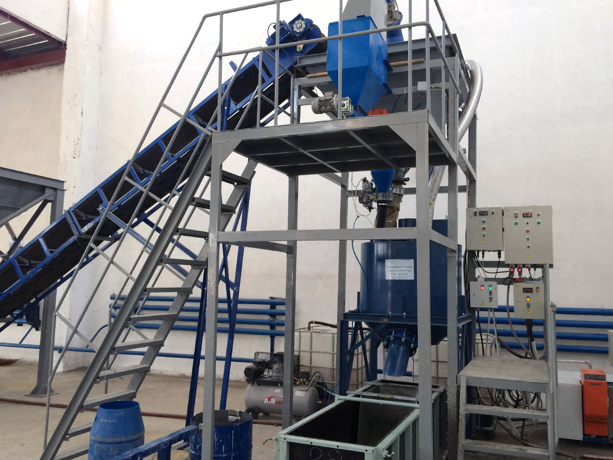
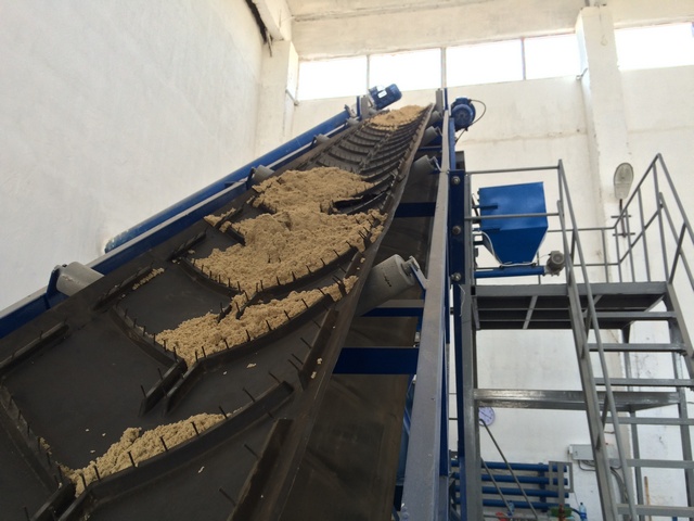
Loading Raw Materials to the Mixer
A weight controller is used to load raw materials (cement, fly ash) to weighers and agents to the weigher of chemical admixtures. Cement, fly ash and admixtures are transported by screw conveyors. The cement and fly ash are now unloaded from the weighers to the mixer. The mortar is stirred for 2–3 minutes to reach homogeneity. When the mortar is ready, admixtures are unloaded to the mixer and the aerated concrete mixture is mixed again for 1–2 minutes.
Operator controls all processes at the mixing area in real time. The operator can use control panel to correct or modify the recipe, the mixing time, and other process parameters.
The equipment supports both manual and automatic modes.
2. Monolith Moulding
When ready, the aerated concrete mixture is unloaded to a 0.85 m3 mould through the mixer valve. The mould is filled at one go. It consists of a foundation and detachable interchangeable sides. Prior to filling, the mould is lubricated and transported to the mixing area to be filled.

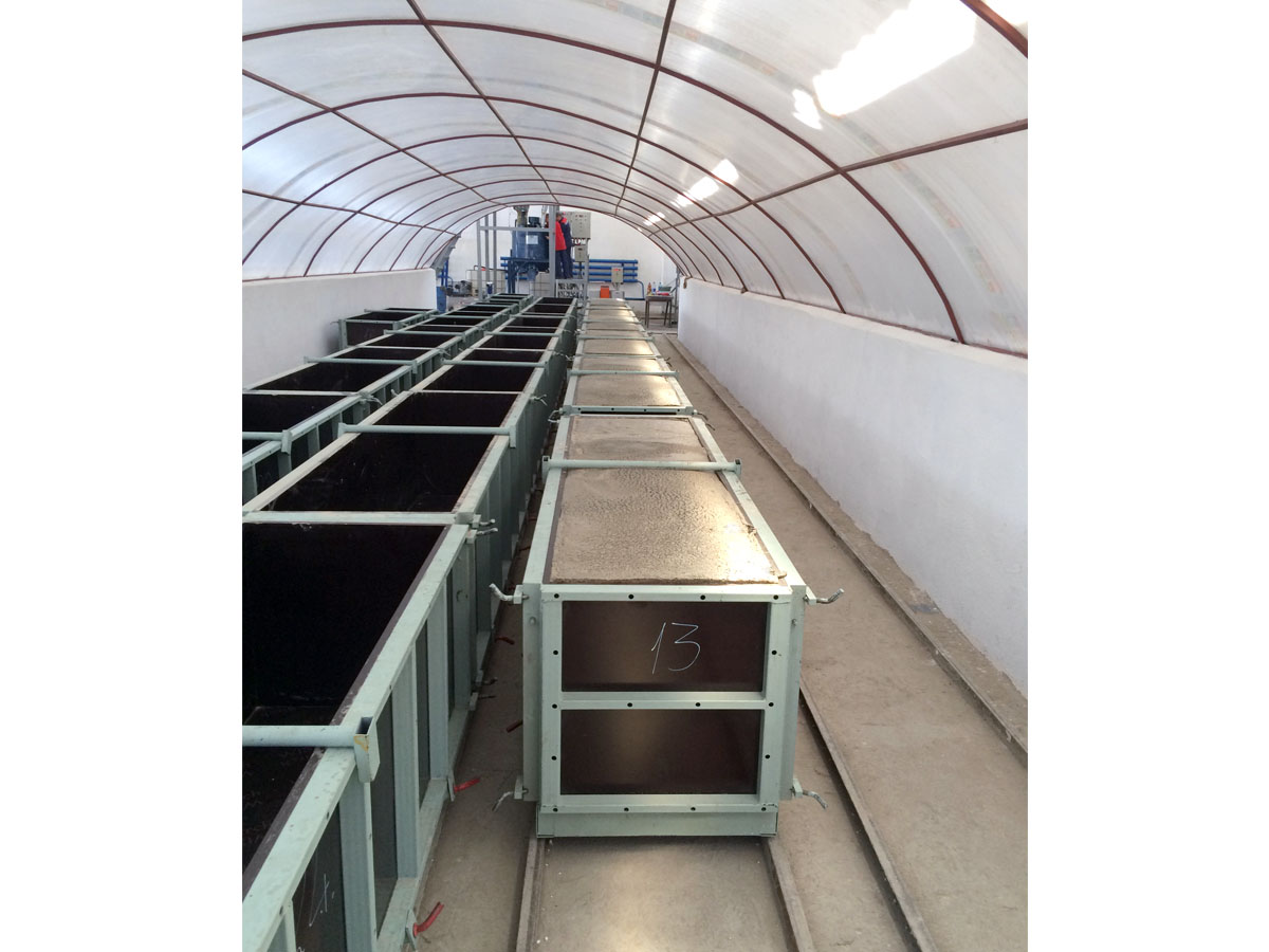
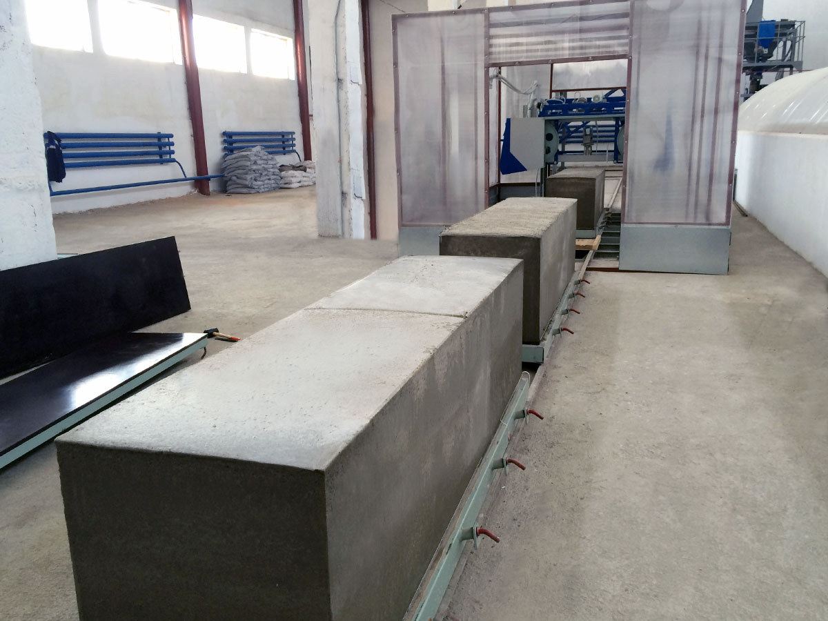
3. Curing the Aerated Concrete Monolith
The filled mould is transported by railings to the curing area (to the heat treatment chamber) where the monolith reaches its stripping strength. Its is recommended for the customer to arrange for sealed tunnel chambers with full heat insulation along all surfaces. The temperature in the chamber should be +30... +40 оС. Achieving the stripping strength may take from 3 to 5 hours and depends on the aerated concrete density, activity, silica type, temperature, etc.
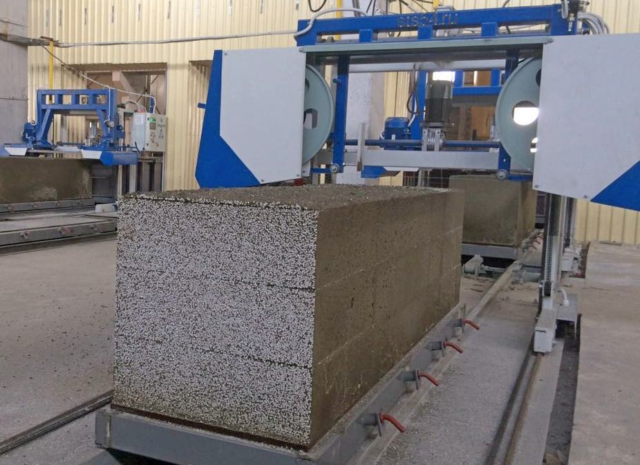
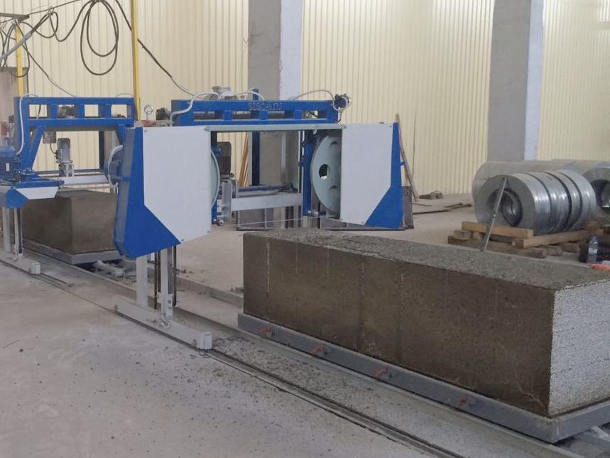
4. Dismantling moulds and cutting massives
After the massif has gained the required strength, the mould containing the massif is transferred to the dismantling machine along the railways, the mould base is held fixed on the railway. Then, the four mould walls are removed and lifted with the gripple. After mould dismantling, the mould base and the massif are transferred to the cutting section. The free walls are then mantled onto a free base, which is on the adjacent railway. The mantled mould is sent to the pouring section. The massif is cut into blocks of pre-set dimensions with АRК-004 cutting unit. At the cutting section, there are two separate consecutive modules for vertical and horizontal cutting of the massif.
The mould base is held fixed with a gripple at the vertical module, while the operator launches the vertical module. Moving along the guides, the module cuts the massif in a vertical plane and trims it on both ends. After vertical cutting, the mould base with the massif is transferred to the horizontal module area, is held fixed with a gripple, after which it is cut in a horizontal plane into the blocks of pre-set dimensions, as well as the bottom layer and the top are cut away. While the horizontal module is in action, the next massif is fed into the vertical module area. So, two massifs are being cut at the same time, which ensures the line high throughput.
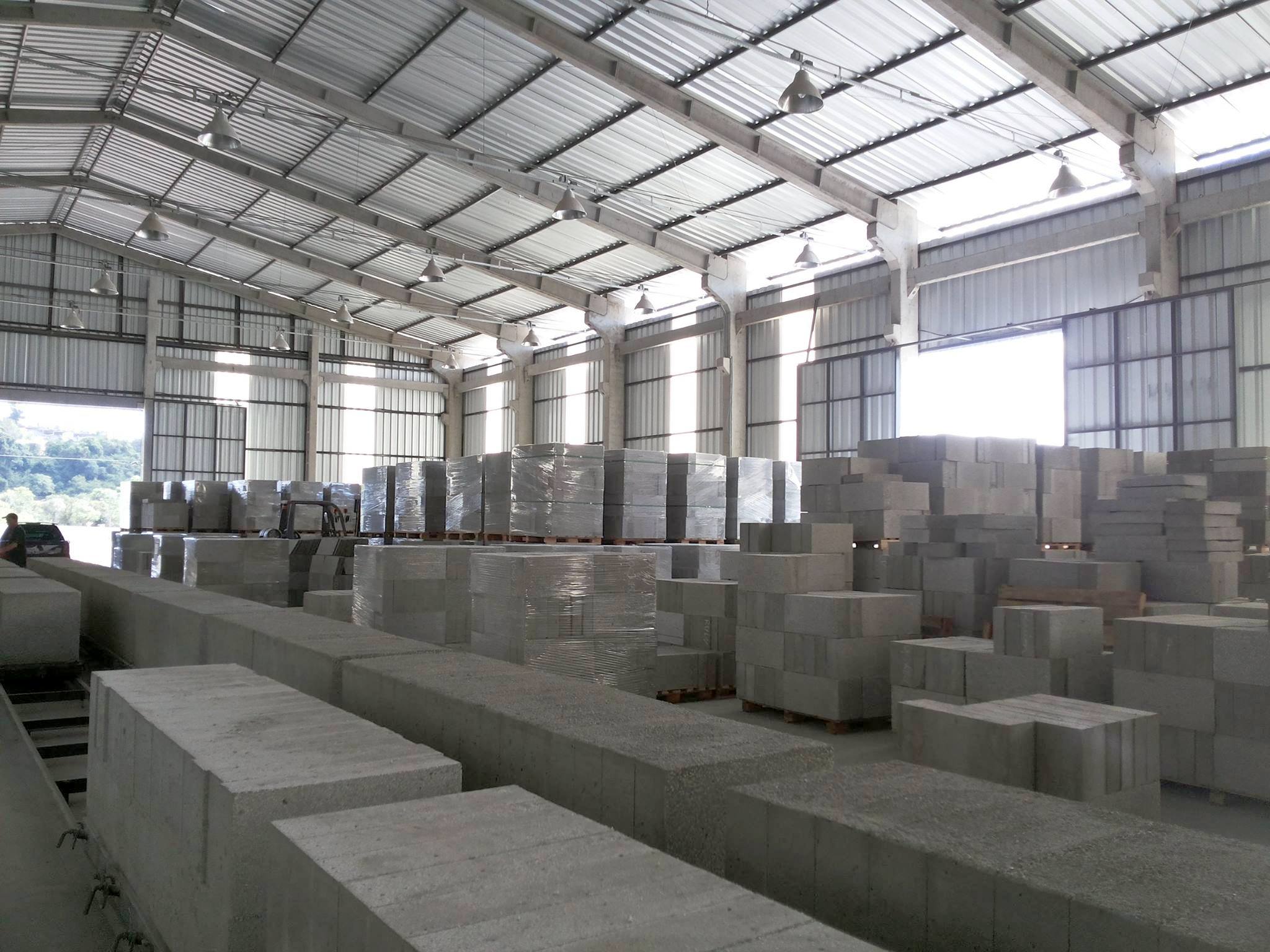
5. Stacking blocks onto pallets, packing, and storing
The mould base with the massif cut is transferred to the block stacking unit. The mould base is held fixed on the railway. Then, half of the massif cut is stacked on a pallet with the help of a gripple. In order to complete the pallet, eight blocks are placed manually. Then, the second half of the massif is stacked, as well as the eight blocks manually (depending on their dimensions). The pallet with blocks is wrapped with a stretching film.

6. Block heat and moisture treatmen
Depending on the climatic zone and type of the material manufactured, the blocks stacked onto pallets can gain the grade strength at the final product warehouse or during heat and moisture treatment. Block heat and moisture treatment is required for accelerating strength gain in the blocks. The heat and moisture treatment means that the blocks are cured in the chamber over 8 to 12 hours at the temperature of +40 to 60оС. The heat and moisture treatment mode also depends on the material density, cement activity and is defined by the customer for each certain type of products manufactured.
7. Recycling the Cutting Waste
The cutting modules cut out the monolith at both ends, at the top, and at the bottom. An innovative solution is to use DG-1 waste grinder to recycle the cutting waste. It allows the aerated concrete waste to be ground into particles of up to 0–30 mm. The ground material can be used as a loose-fill heat insulation for roofs, attics, floor, etc. The grinder makes concrete production almost waste-free.
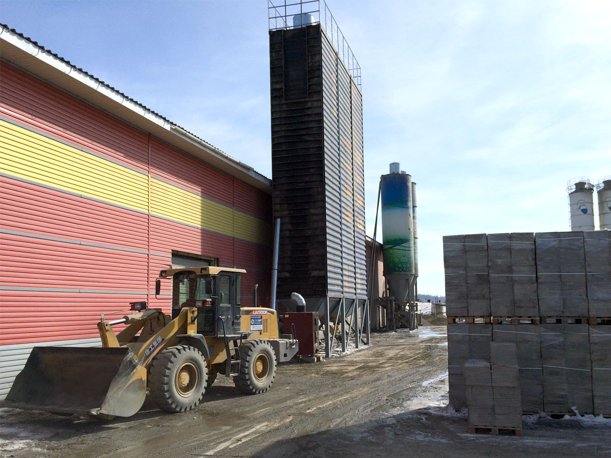
GENERAL
To reduce customer’s expenditures, the line is supplied without cement silo, sand hopper, and railings for mould transportation. The customer is provided with drawings for separate manufacturing of these units.
Besides, the customer is also responsible for water heating up to +35... +40 °C and for arrangement of steam curing chambers. Operating the line in 2 shifts requires additional mould foundations.
The warranty period for the supplied equipment is 12 months. Components of each piece of equipment are listed in the contract, equipment data sheet, and the Delivery and Acceptance Certificate.
Specialists of Siberian Constructing Technologies (SCT) design the layout of equipment in the customer’s production facility. The equipment is installed according to the layout by and at the expense of the customer. The customer is provided with equipment layout (drawings) for corresponding rooms and detailed illustrated instructions for installation.
After the customer completes equipment installation and connection, SCT performs the following works:
• equipment commissioning;• design of aerated concrete;
• optimisation of the production technology;
• customer’s personnel training.
The customer is responsible for compliance to all safety rules, requirements to occupational safety and environment protection as well as to other local regulations.
The customer covers all expenses for SCT personnel transportation and allocation for the period of the works. Technology optimisation includes optimisation of concrete composition based on the raw materials provided by the customer. SCT provides support services.
After equipment commissioning the customer is provided with technical documentation, including:
• technical regulations for productions;• process flow diagram;
• job descriptions;
• safety instructions;
• GOSTs.
TERMS OF DELIVERY
The cost is specified for EXW-Novosibirsk (Russia) and does not include the cost of customs clearance and shipment. The equipment manufacture time: from 30 working days from the advance payment receipt.TERMS OF PAYMENT
Payment 1—70% of the contract value within 5 days from the date the contract is signed.
Payment 2—30% of the contract value within 5 days from the date a confirmation is received that the equipment is ready for shipment.